Real Robotics
We have been operating for many years as an almost “anonymous lab” tucked away in a corner of the Mechanical Engineering building at Leeds University. In 2020, the team and I decided to name the lab Real Robotics and create a website to document our projects, share our experiences and hopefully one day, become a go-to online robotic resource.
The lab quite literally named itself. We make robots to solve real world problems. Over the last 10 years we have created mechanical entities of all different shapes and sizes to complete a wide variety of tasks from surveying to repair. I would say that the 3 main areas of focus of the lab are; exploration, repair, surveying. They are the things that really motivate us.
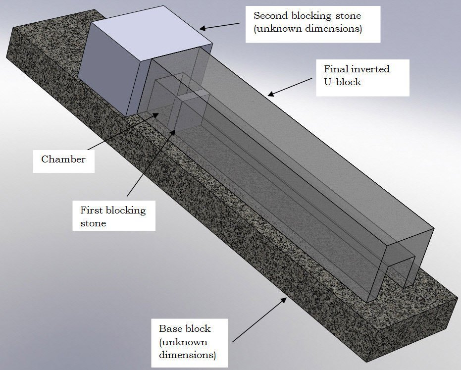
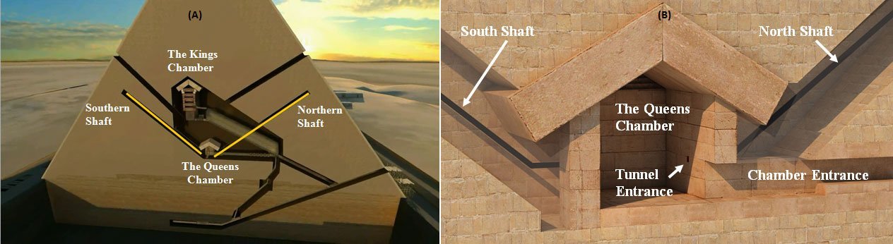
One of our first successful robotic systems was the Djedi robot. In 2010 the 4-wheeled inchworm vehicle successfully made it to the top of a 60 metre shaft inside the Great pyramid of Giza. It went on to explore a hidden chamber and unearth writing hidden for thousands of years.
The variety in our projects keeps us on our toes and we try not to take that for granted. We have explored under the deck plate of HMS Warrior, Queen Victoria’s naval flagship, to evaluate the condition enabling successful restoration funding to be obtained. In Nepal, we have deployed small autonomous surface water vessels to map glacial melt lakes and obtain data to better understand global warming. Recently we have created drones with the ability to repair cracks in roads to stop the formation of pot holes.
Our team is made up of robotic engineers and scientists from the University of Leeds with expertise in robotics, mechatronics, computer science, manufacturing, electronics and systems integration.
The possibilities of robotic technology is enormous and we believe there is no real world problem too complex or challenging. Our aim is simple: to solve problems and we use creativity and applied technology to do that.
If you have a problem that no one else can solve, that has great need to be solved, then contact us at Real Robotics.